Blue Triangle
Rendering a 3D Model from the Terminal without a window manager.
Published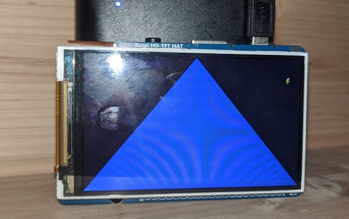
We start off this series of tutorials with the “Hello World” of OpenGL, the blue tirangle. Similar to “Hello World”, this tutorial introduces a lot of questions as to what’s going on under the hood. But those questions will be addressed as we continue with the tutorial. This first example serves as a basis that we can continue to expand upon in further articles. As with each of the articles in this tutoria series, each example can be built with the build.sh script, and then execute with the a.out binary. The output for this article will look like the following.
Drawing our First Triangle
We start off the first tutorial with the “Hello World” of OpenGL which is drawing a single triangle. The first hello world is often the most simple, but somewhat confusing place to start. If you think back to when you first compiled a program, and ran it, you probably had a teacher or text who explained that the code was being compiled down into computer code that could be executed. And you get off into this whole tangent of “what’s going on there?”, before moving onto more syntax. There’s a similar situation where where drawing a triangle brings out a lot of questions about what’s going on under the hood. And I can’t say for certain I’m 100% familiar with how everything works all the way down, so I will provide context where I can, and admit stuff I don’t know in other areas.
All in all the code is pretty long, but pretty straight forward. We have four function prototypes, and our short main function.
So we have four functions, init_ogl, where we will initiate the OpenGL context to be used. Followed by init_shaders where will
sill set up our shaders and triangles to be drawn. And then draw_triangles we will call to actually draw the triangles to the
screen. And the last function is eglGetErrorStr, which isn’t called from main. It’s a debug function called during init_ogl to
take an error code and return the string for the error. In order to manage values that are used in the global scope, we will be using
a struct named state of type GLOBAL_T to manage the namespace.
Initialize OpenGL
To start off we’ll take a look at the init_ogl function. Since not all of the code is needed for the explanation,
... will be used to show where code has been truncated.
The init_ogl function contains a lot of boiler-plate code that’s probably specific to the VideoCore (VC) graphics card.
The most important aspect of the function probably boil down to these lines of code. First we define a list of attributes
that we want to pass into EGL to describe how we want it to behave. Specifically the number of bits we want to use for each
type of color. In this case we use RGBA888. Though I suppose that other common 16 bit profiles like ARGB1555 or RGB565 could
be possible, but I don’t know how interested we are in recreating something like the Sega Saturn or Sony Playstation in practice,
so it seems most common to use the standard RGBA8888 in this case.
From there we create arguments for the context for which OpenGL version we want to work with. I guess for the purposes of the Raspberry Pi, I suppose that means we have the options of working with OpenGL ES versions 1, 2 or 3. In this case we want to use 2. Since it’s easier than starting off with 3 which requires more syntax when using draw calls.
From there we have three functions, eglGetDisplay, eglCreateContext and eglCreateWindowSurface. And these act as you would expect.
The first function eglGetDisplay get’s the current display, such as if the default display is over HDMI or a display hat. For
eglCreateContext is where we tell EGL what version of OpenGL we want to use for that display. And the last function is probably the
least intuitive is eglCreateWindowSurface. The best way I can try to explain this is a “surface” is similar to a list “panels” stacked
on top of each other. So basically we tell EGL that we want to create a new panel, and then place it above the other panels and draw on
it so that it will be use-able to the user.
Syntax for Drawing
Now that we have our OpenGL context set up, we can move on to the actual OpenGL aspect. We start off by creating shaders. And shaders are basically a name for a program that runs on the Graphics Card, and tells the graphics card how to color in pixels or “shade” them. The way this is done is with two shaders, a vertex shader and a fragment shader. The vertex shader describes where things are, and the fragment shader describes what colors these are. So we compile each of these and link them as a program. And then we tell the graphics card which program we want to use.
If you’re wondering at this point, “does that mean we create multiple programs, and switch between them to draw different things?“. The answer is “yes”, but we won’t be needing that for the scope of this tutorial. To start off we’ll use a very simple program. For the vertex shader, we simply want to tell it “use the verex as provided”. And for the fragment shader we will tell it to “draw everything blue”.
In the second half of the init_shaders function is where we actually describe the vertices for the shaders.
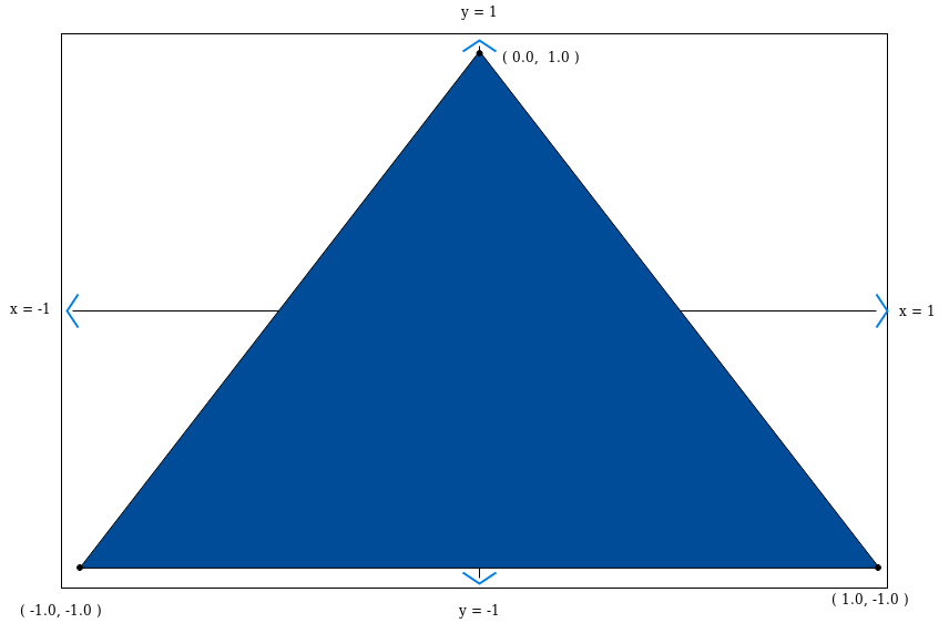
OpenGL uses a cartesian coordinate system by default. Which means that the top of the screen is y = 1, the bottom of the screen is y = -1,
the right side of the screen is x = 1, and the left side of the screen is x = -1. And the center is defined as zero.
So if we use these vertices to draw a triangle, we should get a triangle that spans the width and height of the screen.
And since we told the vertex shader to color in everthing blue, the color should be blue.
In order for the GPU to be able to draw the triangle, we need to save the coordinates of the vertices to the GPU memory. To do that we create a buffer. A buffer is a general term in computing for a continuous list of bytes. In this case each vertex is made up of three float values. Each float value is 4 bytes. So each vertex is 12 bytes (x, y, z) and then we have three vertices, so the buffer will have a length of 36 bytes where we store the vertex coordinates. The buffer itself is just a number value. OpenGL will create a memory space on the GPU where it will save the ammount of bytes you request, and then gives you a number such as “slot 1”, and then says, “if you need to use these again, just ask for slot 1”.
Now that we have a shader program and vertices stored in a buffer on the GPU, then next thing we need to do is define
where the vertices need to be used in the shader program. And the way we do this is by linking an attribute. Basically
an attribute is specific value provided into the shader program for each coordinate. In this case in our shader program
we have the variable attribute vec3 vertex, so we need to tell the program to use our vextex coordinates for that value.
The way this is done is by calling glGetAttribLocation which will store the reference to attribute vec3 vertex,
and then we need to enable it, basically to tell the GPU to expect values to be passed into it.
Which should bring us to our last function draw_triangles. In this function we clear everything from the framebuffer to prepare for drawing.
Then we bind the buffer of the vertex coordinates that we stored with glBindBuffer, we tell the GPU which shader we want to use.
And then last we tell the GPU the type of drawing and the number of points we want to draw for the triangle. Once that’s done we finish,
and swap the framebuffer to display to the user.
Review
If everything worked out, you should be seeing a blue triangle on the screen. With OpenGL there is a lot that needs to come together for everything to work. You need to get the environment working to initialize OpenGL in the first place. You need to write shaders, you need to define attributes to pass into those shaders, and then you need to link these two togehter. And then you need to find the right syntax to be able to actually get something rendered to the screen. And all of this brings up a lot of questions on specically how these different components can be used, what values are expected and how they can be used together. Right now this first example serves as a proof of concept that can be expanded on. And we’ll get to some of those questions in the next articles.