Transform Triangle
Rendering a 3D Model from the Terminal without a window manager.
Published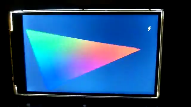
In the previous article, we’ve started to implemented changes that happen during run time. We’ve implemented a fade-in-and-out effect, so naturally the next step is to implement transform. In this article we declare a triangle and then rotate it while moving it left and right across the screen. The output for this article is given below.
In this article we will be introducing transformations, which is one of the most common effects used in 3d graphics. If you have a cube or any 3d object, you generally have three main transformations that you can apply to that object. You can scale it to either increase or decrease the size. You can move it in a certain direction, which is specfically called translation. And you can rotate the object across a specific axis. In order to do this we will we what it called a transformation matrix. In this article we want to apply two transformations. A translation in the X axis to move the triangle back and forth. And a rotation in the Z axis to spin the triangle around towards the camera. Let’s start off by looking at the vertex and fragment shaders.
Already in the vertex shader we see something new.
We’re using a new variable type called mat4. The mat4 variable type is a 4x4 matrix comprised of 16 float values.
We can also see that it’s a uniform value which means it retains its value until it’s updated again.
The name mvp is actually kind of wrong. To give sme hints, for OpenGL we have Projection, View and Model matrices.
The idea of a mvp matrix is to have all of these calculated together as opposed to multiplying them in the shader.
In this case since we’re only transforming our triangle or “model”, it should be a model_matrix.
Maybe this mistake provides a little bit of incite or hints of how the shader should be structured.
Looking at the other line that has been updated we have gl_Position = mvp * vec4(coord2d, 0.0, 1.0).
What’s happening here is to say, “the position of the triangle should be the position of the triangle coordinates,
multiplied by this mvp transformation matrix”. So let’s take a second to talk about the transformations.
When it comes to transformations, there’s a reason that we use this approach. Basically when we bind the vertices of the triangle (or our model) to the buffer there’s no loose the ability to work with the vertices outside of the shader. We need to have a method to apply changes to the vertices during runtime. And the way we do this is with a 4x4 matrix. Well honestly we don’t really need to a matrix. In terms of translataion and moving an object forward or back what we’re doing is adding a specific value to the original position of the vertices. So if we move the triangle up by 3 units, then the add 3 to each one of the Y vertices in the original model. If we move that down a little bit, then we add something like 2.5 to each matrix. So translation is simply adding a value to a given axis to move the model in that direction.
For rotation, we don’t really need a matrix either. You could do the math to multiply by sin and cos for each axis. I would post the equation here, but I haven’t done real math in a while and can’t remember the formula. In terms of using 4x4 matrices there are two advantages. The first advantage is we can “encode” the translations into a single 4x4 matrix. Say that for instance we need to scale, translate and rotate a triangle in each dimension. That’s 9 different equations that we would need to write into our shader. When using a 4x4 matrix we can bake all of these in. To as single 4x4 matrix and have a single variable in our shader. And the other advantage of using a 4x4 matrix is that it gives us a pretty easy way to easy multiply through a lot of equations in a standard format, which is what graphics cards are specifically designed to do.
Quick check on the fragment shader. Nothing new, so let’s look into what’s different in main.
Also not much new in the init_buffers as it mostly resembles the fade example from the previous article.
Which means that everything is happening in the draw_trianlges function.
For the rotation, we can simply abuse degrees. We can increment the rotation by 1 degree for each frame that is rendered, and then convert that to radians. For position we can take advantage of the fade approach we made in the previous article. Because we are moving the triangle from -1 to 1, we can increment the position by a specific amount each time, and then flip the direction of the incrementation once the position reaches either limit.
Then we go ahead and create the matrix to pass into the shader. First we create a vector for the position.
As we’re working in the x-direction vec3 t = { state->pos, 0.0f, 0.0f } we create a three length array with the position
in the x-axis index.
Next we create an identity matrix for the mvp matrix that we are going to pass into our shader.
After that we create a matrix for z rotation. And then we create a matrix for the position.
Then we go ahead and multiply the mvp matrix by the rotation matrix. And then we multiply the mvp matrix by the translation matrix.
This is effectively a way to encode the transformations into a single array of values, so they can be passed into the shader.
The syntax for updating the uniform in the shader is with glUniformMatrix4fv(state->uniform_mvp, 1, GL_FALSE, mvp).
Review
One thing that I didn’t cover and still confuses me is the vertex color. We define a different color for each one of the triangles vertices, and the fragment shader will blend each of the colors into each other. The problem is that we never eplictly wrote this blend equation into out shader. The vertex shader should be taking a color value as an attribute and passing that exact value into the shader for each fragment. But then we each fragment is drawn the vertex color seem to automatically transition between each triangle over the face. Not going to complain because it looks cool, but I’m not sure specifically when or why it happens.